The NB HMI series has the possibility to connect with Omron PLCs and devices through Ethernet, and Serial interfaces, particularly the Omron CP1L compact PLC’s and the CJ1/CJ2 modular PLC’s, as well as automation components from other vendors.
This article explains the different options that are available and how connection with CP1L and CJ is setup (separate articles) using Host Link and Ethernet.
Content
1. Connecting Methods
2. Serial Communication Connection
3. Modbus protocol
4. FINS/UDP Communication Connection
5. Example programs
1. Connecting Methods
RS232C
RS-232C is a kind of serial physical interface standard formulated by Electric Industry Association (EIA). RS-232C method is based on 1:1 communication, which is generally applied to the point-to-point communication within 15 meters due to the existence of common-ground noise and the unavoidable common-mode interference etc.
RS485
RS-485 uses the differential signal negative logic and the common 2-wire method, and the connectable node on the same bus is up to 32. The master-slave communication method, i.e. one master communicating with multiple slaves, is generally used in the RS-485 communication network.
RS-485 and RS-422A methods can realize 1:N communication, i.e. one host communicating with multiple PLCs or PTs. The maximum number of PLCs or PTs that can be connected to the host is up to 32, and the maximum transmission distance is 500 meters.
RS-485 is half-duplex communication method that cannot allow the transmission and receiving to be performed simultaneously.
RS422
It is unnecessary to control the data direction due to 4-wire RS-422A interface using separate transmission and receiving channels. Any necessary signal exchange among the equipment’s can be performed by using software method (XON/XOFF Handshaking) or hardware method (one separate twisted-pair cable).
RS-422A standard with its full name "Electrical Characteristics of Balanced Voltage Digital Interface Circuits" specifies the characteristics of the interface circuit. Actually, there is also a signal ground, totaling 5 wires. Because the receiver uses high input impedance and the driving performance of the transmission driver is more powerful than that of RS-232C, therefore the same transmission wire can be connected with multiple receiving nodes, and the number of the connectable node is up to 10. That’s to say, one is the master and the others are the slaves. Due to the communications are impossible among the slaves, therefore the RS-422A supports one-point-to-multiple full-duplex communications.
Ethernet
Ethernet is a kind of baseband LAN specification, established by Xerox company and jointly developed by Xerox, Intel and DEC companies, which is the most common communication protocol standard adopted by the existing LANs. PT uses the standard UTP as the transmission media for the Ethernet.
The network communications between PT and PLC can be realized through the Ethernet connection. The user can read the communication data by connecting the PT with OMRON PLC supporting FINS/UDP via the Ethernet regardless of the communication protocol for the built-in Ethernet device in the PLC. What's more, connecting the PT with PC via the Ethernet can also perform the project upload/download and the system processing.
Communicating with the PLC Manufactured by Other Companies.
Besides the connection with the PLC manufactured by OMRON, NB-Series PTs can also communicate with the PLCs manufactured by SIEMENS, Mitsubishi Electric Corporation, Schneider Electric, Ltd., Delta, Panasonic, Allen-Bradley, GE Fanuc Automation Inc., LG and the PLCs supporting Modbus protocol. For the manufacturers and the models of the PLCs that can be communicated with, refer to
[NB Series Host Connection Manual].
2. Serial Communication Connection
Host Link Connection Method
Host Link is a connection method in which one PLC is connected to one NB Unit. There are 2 kinds of connection methods: RS-232C and RS-422A.
The RS-232C connection method using serial ports COM1/COM2
This is the simplest and most feasible method.
The following cables are recommended.
XW2Z-200T (Cable length: 2m) by OMRON
XW2Z-500T (Cable length: 5m) by OMRON
The RS-422A connection method using the serial port COM2
With this method, the communication distance can be extended to a maximum of 500m.
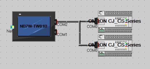
The following cables are recommended.
NB-RSEXT-2M (Cable length: 2m) by OMRON
Note: Use 4-wire RS-422A connection, Host Link does not support 2-wire RS-485 connection.
3. Modbus Protocol
Introduction to Modbus Protocol
Modbus is a kind of request/response protocol, providing the service specified by the function codes. Modbus protocol including ASCII, RTU and TCP modes etc. does not specify the physical layer, but defines the message structure identified and used by the controllers regardless of communication through what kind of network. ASCII, RTU modes included in Modbus protocol specify the structures of message and data, commands and the response methods. The data communication adopts Master-Slave mode: the master sends out the data request message(s) first, and then the slave sends the data to the master in response to the request after receiving the correct message(s); the master also can directly send the message(s) to modify the data in the slave, thus realizing the two-way reading/writing.
Modbus specifies that only the master has the initiative while the slave can only make response passively, including answering the error message(s).
When NB-series HMIs perform communications by Modbus protocol, it follows the standard Modbus communication process.

Address code
The data field in the message frame contains two characters (ASCII) or 8 bits (RTU). The possible slave device addresses range from 0 to 247 (decimal), and the single device addresses range from 1 to 247. The master device selects the slave device through the data field in the message, where addresses of slave device(s) to communicate with the master are put. When sending back the response message(s), the slave device puts its own address into the data field of the response in order to make the master know which device has made the response. Address 0 is used as the broadcast address in order to make all the slave devices identify it.
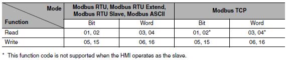
Function code
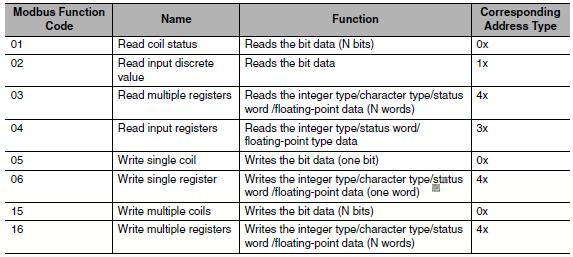
The read/write function codes corresponding to each mode are as follows:
Data area
The data area includes the data needed by the terminals to perform the specific functions or the data sampled during the terminal responding to the query. These data may be the number, reference addresses or set values. For example, when the function codes inform the terminal to read one register, the date area needs to specify which register the data is read from and how much data to be read. The imbedded address and the data type vary with the slave contents.
Error checking code
Modbus protocol specifies that the data needs to be checked: besides the parity check for serial protocol, ASCII mode adopts LRC check, and RTU mode adopts 16-bit CRC check, while TCP mode has no requirements for extra check.
When NB adopts Modbus TCP protocol (Master/Slave mode)
When the PLC and the HMI are connected via the Modbus protocol, 2 situations exist depending on the master and slave statuses of the devices.
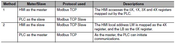
(1) HMI as the master, and PLC as the slave (HMI adopts Modbus TCP protocol)
The PLC and the HMI communicate via the standard Modbus TCP protocol, with the HMI as the master control terminal and the PLC as the slave terminal. The PLC should support the Modus TCP Slave protocol, and also map out the 0X, 1X, 3X and 4X registers (hereof, the 0X and 1X are bit registers, while 3X and 4X are word registers.)
(2) PLC as the master, and HMI as the slave (HMI adopts Modbus TCP protocol)
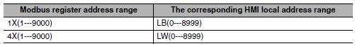
The PLC and the HMI communicate via the standard Modbus TCP protocol, with the PLC as the master control terminal and the HMI as the slave terminal. The PLC should support the Modbus TCP protocol. The HMI local addresses LW and LB are mapped as the 4X and 0X registers, written and read by the PLC.
The corresponding relations of the registers are as below:
Modbus RTU
This is used in serial communication & makes use of a compact, binary representation of the data for protocol communication. The RTU format follows the commands/data with a cyclic redundancy check checksum as an error check mechanism to ensure the reliability of data. Modbus RTU is the most common implementation available for Modbus. A Modbus RTU message must be transmitted continuously without inter-character hesitations. Modbus messages are framed (separated) by idle (silent) periods.
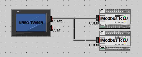
When Using Modbus RTU Protocol
HMI default communication parameters: 9600bps (Baud Rate), 8 (Data Bit), even (Parity Check), 1 (Stop Bit) and 1 (PLC Station No.)
Note:
1 Modbus RTU protocol supports broadcast station number, but the broadcast function only supports the write operation only i.e. the broadcast function cannot be used for the components with read attribute.
2 The broadcast function has two usage methods.
(a) For the components with write-only attribute (Bit State Setting component and "Toggle" excluded) and the Multiple State Setting components ("Add value", "Sub value", "JOG++" and "JOG--" excluded)
(b) Use Macro instruction in the Macro programming to perform the write operation for the address of the Broadcast Station No.
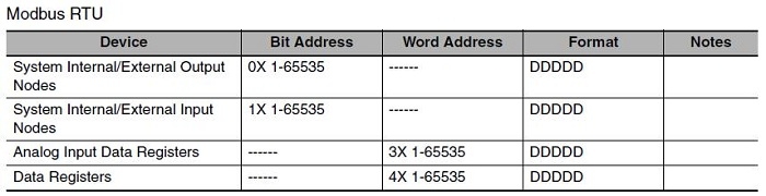
Supported registers
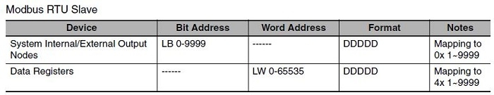
Modbus RTU Slave
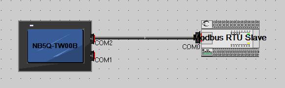
When Using Modbus RTU Slave Protocol
HMI default communication parameters: 9600bps (Baud Rate), 8 (Data Bit), even (Parity Check), 1 (Stop Bit) and 1 (PLC Station No.)
Supported registers
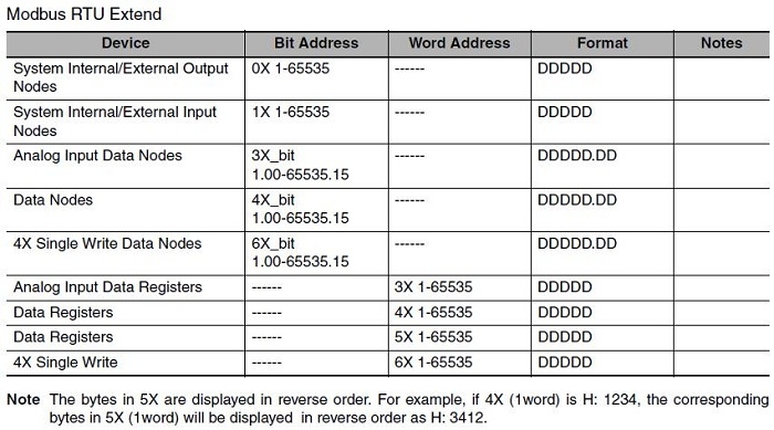
Modbus RTU Extend
When Using Modbus RTU Extend Protocol
HMI default communication parameters: 9600bps (Baud Rate), 8 (Data Bit), even (Parity Check), 1 (Stop Bit) and 1 (PLC Station No.)
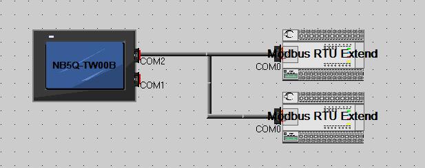
Supported registers
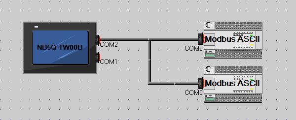
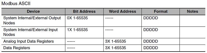
Modbus ASCII
This is used in serial communication & makes use of ASCII characters for protocol communication. The ASCII format uses a longitudinal redundancy check checksum. Modbus ASCII messages are framed by leading colon (':') and trailing newline (CR/LF).
When Using Modbus ASCII Protocol
HMI default communication parameters: 9600bps (Baud Rate), 8 (Data Bit), even (Parity Check), 1 (Stop Bit) and 1 (PLC Station No.)
Supported registers
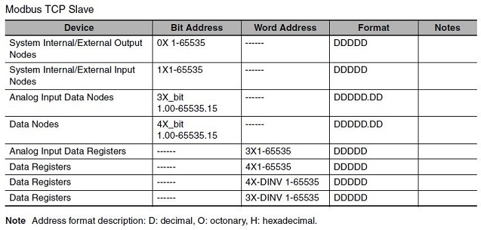
Modbus TCP/Slave
This is a Modbus variant used for communications over TCP/IP networks, connecting over port 502. It does not require a checksum calculation as lower layers already provide checksum protection.
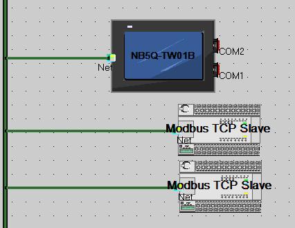
When Using Modbus TCP Slave Protocol
HMI serves as the master, the network configuration is as follows.
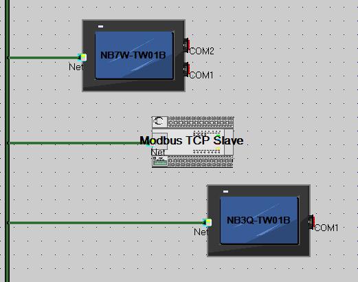
When Using Modbus TCP Protocol
HMI serves as the slave, the network configuration is as follows.
Supported registers
4. FINS/UDP Communication Connection
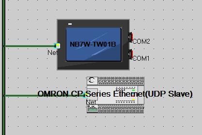
Connecting to Host via Ethernet
To connect to the network using Ethernet, the network number, node number, and IP address must be set. Use the NB-Designer to set the settings. (The default IP address of HMI Unit is 192.168.250.1.)
Connecting PT Directly to the Host
Connect the NB to the host using twisted-pair cable.

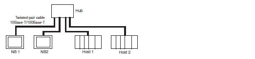
Connecting PT to Host with a Hub
Multiple NBs and hosts can be connected using twisted-pair cable and a hub.
The Ethernet FINS communication for NB series products is only limited the local network, but the Ethernet communication cross the network segment is allowable with the prerequisite of using the router. That’s to say, the supported FINS network is only limited to the local network, but the various devices in the network can be cross the network segment. Please take the following architecture as reference.
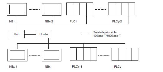
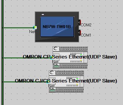
X represents the amount of NB series products, and y represents the amount of PLC. The relationship between x and y must meet the following conditions:
• x 1
• y 1
• x + y 33
In this system architecture, the system has only one network number. And the unique ID, i.e. Node ID, is assigned to both NB and PLC in the system.
When the actual amount of configured devices (NB series products + PLC) is greater than 33, the customer can create a new NB-Designer project to handle this problem.
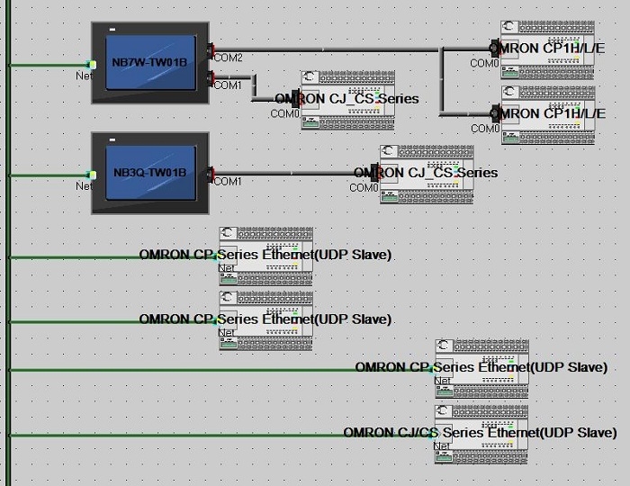
Note: OMRON Ethernet UDP communication protocol, both CJ/CS Series and CP Series, are FINS/UDP protocol. The difference between these two protocols is only in the address range of the channel.
5. Examples programs (Articles)
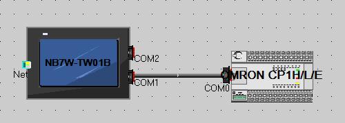
Host Link (RS232C)
NB with CP1L through COM1/RS232 (Host Link)
![]() NB_With_CP1L_Through_COM1-RS232(Host_Link).zip
NB_With_CP1L_Through_COM1-RS232(Host_Link).zip
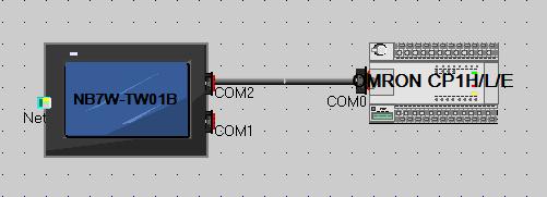
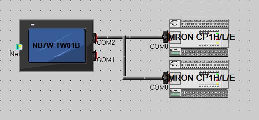
Host Link (RS422)
NB with CP1L (2pcs) through COM2/RS422 (Host Link)
![]() NB_With_CP1L_(2pcs)_Through_COM2-RS422(Host_Link).zip
NB_With_CP1L_(2pcs)_Through_COM2-RS422(Host_Link).zip
Host Link (RS232C) and Modbus RTU(RS485)
NB with CP1L through COM1/RS232 (Host Link) and MX2 (2pcs) through COM2/RS485 (Modbus RTU)
![]() NB_With_CP1L_Through_COM1-RS232(Host_Link)_And_MX2_(2pcs)_Through_COM2-RS485(Modbus_RTU).zip
NB_With_CP1L_Through_COM1-RS232(Host_Link)_And_MX2_(2pcs)_Through_COM2-RS485(Modbus_RTU).zip
Ethernet (FINS/UDP)
NB with CP1L-EM (2pcs) through Ethernet (FINS/UDP)
![]() NB_With_CP1L-EM_(2pcs)_Through_Ethernet(FINS-UDP).zip
NB_With_CP1L-EM_(2pcs)_Through_Ethernet(FINS-UDP).zip
Ethernet (FINS/UDP)
NB with CP1L-EM and CJ2M-CPU33 through Ethernet (FINS/UDP)
![]() NB_With_CP1L-EM_And_CJ2M-CPU33_Through_Ethernet(FINS-UDP).zip
NB_With_CP1L-EM_And_CJ2M-CPU33_Through_Ethernet(FINS-UDP).zip
Ethernet (FINS/UDP) and (Modbus/TCP)
NB with CP1L-EM(FINS/UDP) and SMC-EX250(Modbus/TCP)
![]() NB_With_CP1L_(FINS-UDP)_and_SMC_(Modbus-TCP).zip
NB_With_CP1L_(FINS-UDP)_and_SMC_(Modbus-TCP).zip
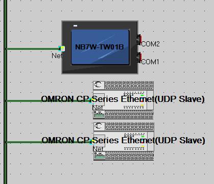
Ethernet (FINS/UDP)
How To Connect Two NB HMIs To a CP1 PLC over Ethernet(FINS-UDP)
![]() Two_NB_HMIs_to_a_CP1_PLC_over_Ethernet(FINS-UDP).zip
Two_NB_HMIs_to_a_CP1_PLC_over_Ethernet(FINS-UDP).zip
NB-series Manuals (included in NB-designer)
Programmable Terminals Host Connection Manual (Cat. No. V108)
Programmable Terminals NB-Designer Operation Manual (Cat. No. V106)
Programmable Terminals Setup Manual (Cat. No. V107)
Programmable Terminals Startup Guide Manual (Cat. No. V109)