Operation detail
Menu bar
[File] Menu
[End]
Terminate FJ software.
[Function] Menu
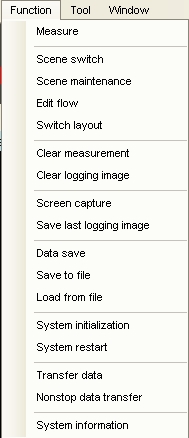
[Measure]
Execute measurement.
[Scene switch]
Show dialog for switching scene and scene group.
[Scene maintenance]
Show dialog for scene maintenance.
[Edit Flow]
Show flow edit window.
[Switch layout]
Show dialog for switching screen layout.
[Clear measurement]
Clear measurement results.
[Clear logging image]
Clear logging images.
[Screen capture]
Execute screen capture.
[Save last logging image]
Save last logging image as file.
[Data save]
Save all setting data.
Saved data is automatically loaded on next start up.
[Save to file]
Save all setting as file.
[Load from file]
Load setting from file.
[System initialization]
Execute system initialization.
[System restart]
Restart the system.
[Transfer data]
Transfer data for preparing non-stop adjustment.
Refer to  non-stop adjustment for detail.
[Transfer non-stop data]
Apply the parameter which is changed by non-stop adjustment to system.
Refer to non-stop adjustment for detail.
[System information]
Show system information.
[Tool] menu
External tools registered toolmenu.ini are shown, and can be launched from this menu.
About toolmenu.ini, refer to Appendix:Description of configuration files.
[Window] menu
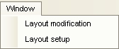
[Edit layout]
Switch to Edit Layout mode.
[Set layout]
Show layout setting dialog.
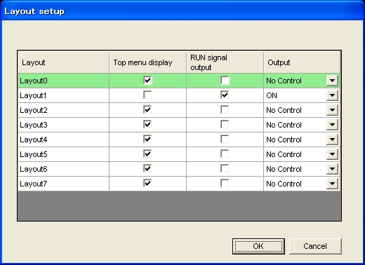
Each layouts have these setting items.
| Upside menu display |
If this is set OFF, the menubar is not displayed and that makes impossible to edit layout. |
| RUN signal uotput |
If this is set ON, RUN signal is ON while this layout is selected. |
| Output |
If this is set ON, FJ system outputs measurement results. |
In case there are no possiblity to switch to the layout No. which can modify layout (for example, "Upside menu display" of all lyouts are set to OFF") and you need to modify layout, delete system data file and restart FJ software. By doing this, all the layouts will be initialized. However, all of the system data is initialized as well.
[Window list]
Show list of windows on the screen.
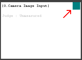
Image Window and Image Container Window
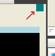
When the button on right-top corner of Image Container Window is pressed, Image Container Window switches to configuration mode.
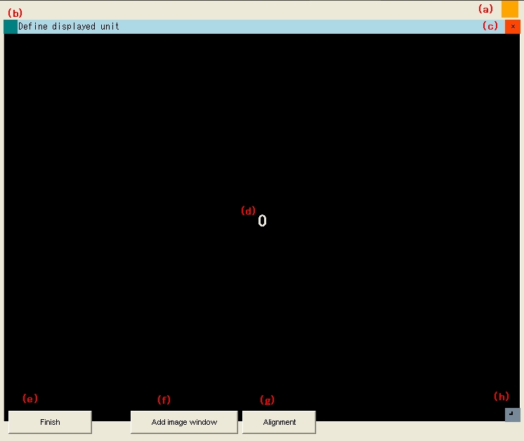
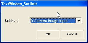
(b) When this button is pressed, show dialog to configure each Image Window.
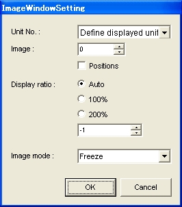
Configurable items are as below :
| Item |
Description |
Value |
|---|---|---|
| Unit No. |
Unit to display results |
"Linked flow display" or unit number |
| Image |
Sub image number to display |
0 - 100 |
| Positions |
Opetion to display multiple units |
ON/OFF |
| Zoom rate |
Zoom rate |
Auto 25% 50% 75% 100% 125% 150% 175% 200% |
| Image mode |
Image display mode |
Through Freeze LastNG |
(d) Show image number of Image Window.
(e) Exit configuration mode.
(f) Add new Image Window.
(g) Align Image Windows.
(h) Dragging this area changes the size of display Image Window.
Measure Window
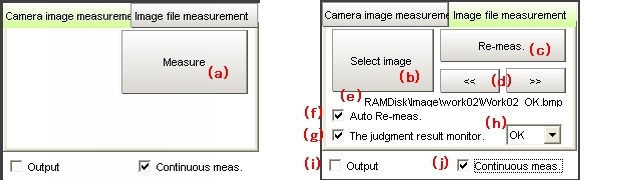
When (j) is checked, measure continuously.
(b) Select image files or logging image files in the system memory.When (f) is checked, remeasure the selected image file.
(c) Remeasure the selected image file.When (j) is checked, remeasure the image files in the same folder sequentially.
When (f) is checked, remeasure the selected image file.
(e) Display the information of selected image file.(f) Options of auto-remeasure.
When checked, click b or d, select image file and remeasure.
(g) (h) Check this option when want to stop remeasureing under a condition.When (g) is checked, remeasure image files continuously.
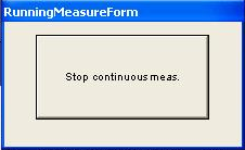
When the condition displayed in (h) is fit, display the dialog below.
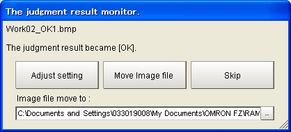
- [Adjust setting] : About remeasureing.
- [Move Image file] : Move Image file to selected folder, and continue remeasureing.
- [Skip] : Continue remeasureing.
(i) When checked, output the measurement result to external devices.(j) When checked, display the dialog below and measure continuously.
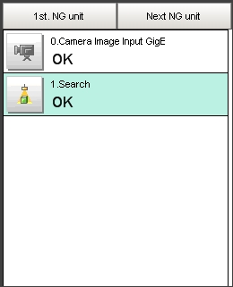
Flow window
This area shows measurement flow and judge results of each processing units.
Detailed result window
Detailed measurement result of selected processing unit is displayed by text.
This button shows the dialog to configure detailed result window.
Configurable items are as below :
| Item |
Description |
Value |
|---|---|---|
| Unit No. |
Unit to display results |
"Linked flow display" or unit number |